Monday, February 3, 2020

ESP8266-based WiFi MQTT air quality monitoring system using PMS7003 sensor

Introduction


Low-cost (US$19) MQTT Air Quality Monitoring System


Purpose


The aim of this project is to use PMS7003 sensor to measure air quality and publish data to MQTT broker.

Features


This project is based on our previous project named "ESP8266-based air quality monitoring system using PMS7003 sensor". It adds MQTT functionality to publish measured data to the MQTT broker. Especially, io.adafruit.com offers a free account, which is good enough for prototyping IoT device easily.

Prerequisites


- Arduino IDE
- Adafruit MQTT Library(We can install this from Library Manager in Arduino IDE)
- ESP8266 package for Arduino IDE
- io.adafruit.com free account

Requirements


Hardware
-Wemos D1 mini : US$1.77 on Aliexpress
-PMS7003 air quality sensor : US$16.80 on Aliexpress

Instructions


Step 1. Setup hardware

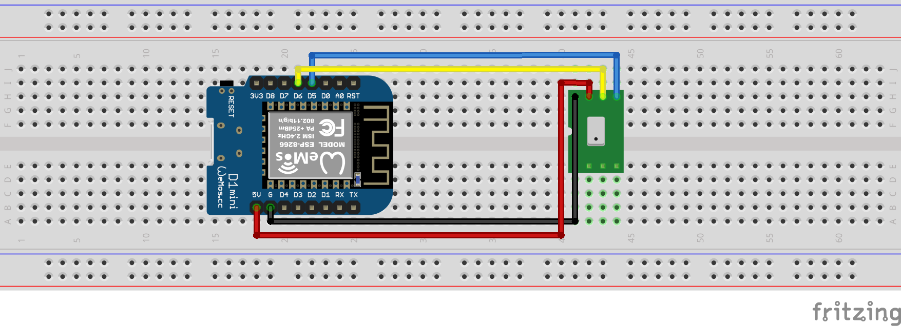
PMS7003 sensor comes with a small breakout board, which has TX, RX, VCC, GND pins. Connect TX of PMS7003 to D5 of Wemos, RX to D6, VCC to 5V, and GND to G. Finally, connect micro usb to Wemos for uploading firmware, and check serial monitor and serial plotter in Android IDE to make sure the sensor works correctly.


Step 2. Create io.adafruit.com free account and feeds. Additionally, create a dashboard to show the value of feeds.

In this project, we will create  3 feeds. Each feed stores value for PM1.0, PM2.5, and PM10.0, respectively. We will use the 'Key' of each feed in our sketch to publish new value to MQTT broker.


After creating feeds, click 'AIO Key' menu to find out IO_USERNAME and IO_KEY value, which we will use in our sketch.

Step 3. Upload sketch to Wemos D1 mini

In the following sketch, four values need to be modified with your own.

- WIFI_SSID    : Name of WiFi router
- WIFI_PASS    : Password of WiFi router
- AIO_USERNAME : Value of 'IO_USERNAME' of MQTT broker
- AIO_KEY      : Value of 'IO_KEY' of the MQTT broker

For WiFi feature, three functions are added to the sketch of our previous project.

- connectWifi() : Connect to WiFi router
- connectMQTT() : Connect to MQTT broker
- publishMQTT() : Publish to MQTT broker


Results


After uploading firmware, Wemos restarts itself automatically. Once Wemos D1 mini has restarted, serial monitor shows air quality data from PMS7003 every 5 minutes. In the following serial console output, it shows MQTT server is connected and published 3 feeds successfully.


On MQTT broker website, we can check the data which is sent from device. In the menu, go 'Feeds', then, click the name of feed to see the line graph of published value.


Additionally, we can create a dashboard to display all related feeds in a single screen such as following screenshot. In the dashboard, it shows value of PM1.0, PM2.5 and PM10.0 altogether.


References


Source codes at github

ESP8266-based WiFi air quality monitoring system using PMS7003 sensor

Introduction


Low-cost (US$19) WiFi Air Quality Monitoring System


Purpose


The aim of this project is to use PMS7003 sensor to measure air quality and transmit data to ThingSpeak IoT cloud platform via WiFi.

Features


This project is based on our previous project named "ESP8266-based air quality monitoring system using PMS7003 sensor". It adds WiFi functionality to send measured data to the IoT cloud. Especially, ThingSpeak offers a free account, which is good enough for prototyping IoT device easily.

Prerequisites


- Arduino IDE
- ESP8266 package for Arduino IDE
- ThingSpeak free account

Requirements


Hardware
-Wemos D1 mini : US$1.77 on Aliexpress
-PMS7003 air quality sensor : US$16.80 on Aliexpress

Instructions


Step 1. Setup hardware

PMS7003 sensor comes with a small breakout board, which has TX, RX, VCC, GND pins. Connect TX of PMS7003 to D5 of Wemos, RX to D6, VCC to 5V, and GND to G. Finally, connect micro usb to Wemos for uploading firmware, and check serial monitor and serial plotter in Android IDE to make sure the sensor works correctly.


Step 2. Create ThingSpeak free account and channel

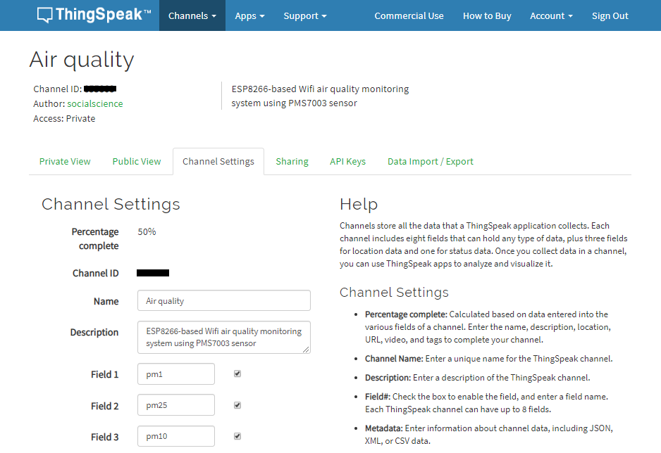
In this project, we will create a channel with 3 fields. Each field stores value for PM1.0, PM2.5, and PM10.0, respectively.


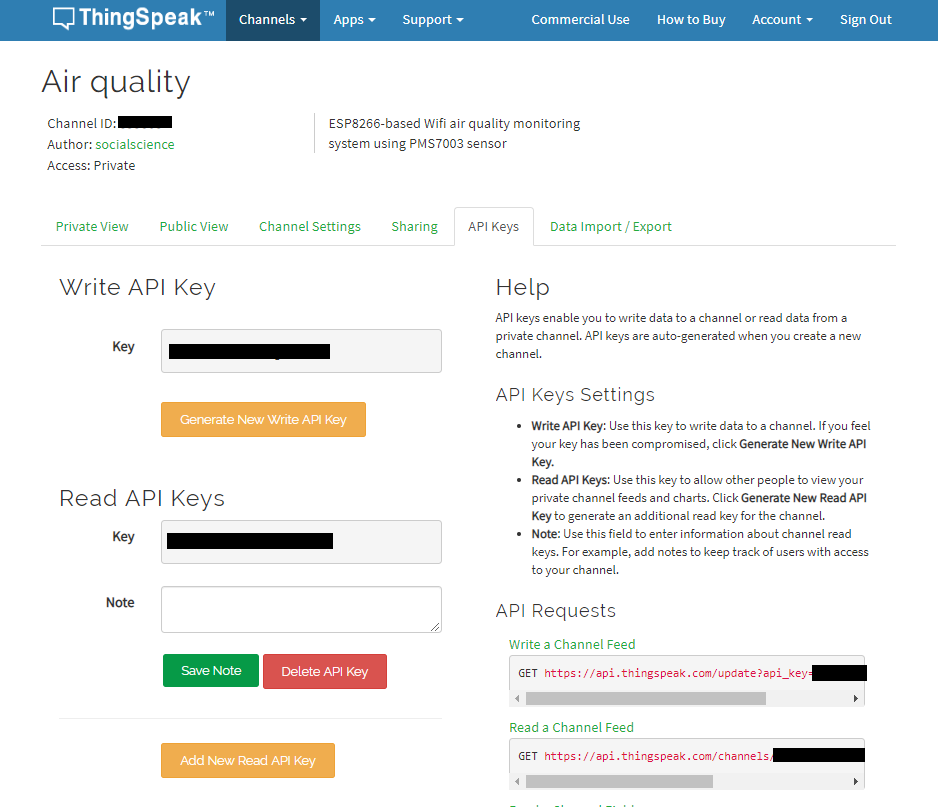
After creating a channel, click 'API Keys' menu to find out 'Write API Key' value, which we will use in our sketch.


Step 3. Upload sketch to Wemos D1 mini

In the following sketch, three values need to be modified with your own.

- WIFI_SSID : Name of WiFi router
- WIFI_PASS : Password of WiFi router
- TS_KEY    : Value of 'Write API Key' of the channel

For WiFi feature, two functions are added to the sketch of our previous project.

- connectWifi() : Connect to WiFi router
- uploadCloud() : Upload measured data to ThingSpeak cloud using HTTP GET request


Results


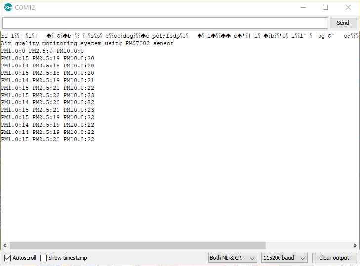
After uploading firmware, Wemos restarts itself automatically. Once Wemos D1 mini has restarted, serial monitor shows air quality data from PMS7003 every 5 minutes. In the following serial console output, it shows a HTTP GET request and response from ThingSpeak.


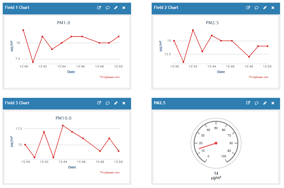
On ThingSpeak website, we can check the data which is sent from device. In the menu, go 'Channels/My channels', then, click 'Private' submenu of the channel. By default, it will show you line graph of each individual field. By clicking 'Add Widgets' menu, you can create a gauge widget as well. For example, in the following screenshot, the bottom right gauge is added manually to make it easier to read for users.


References


Source codes at github

Sunday, February 2, 2020

ESP8266-based air quality monitoring system using PMS7003 sensor

Introduction


Low-cost (US$19) Air Quality Monitoring System


Purpose


The aim of this project is to use PMS7003 sensor without 3rd party library. Additionally, it allows delay function in the loop and demonstrates how to communicate with sensor via software serial.

Features


- delay function : Some example codes on Internet do not work with delay in loop and generate endless checksum error. That is caused by serial buffer overflow between PMS7003 and Wemos. To avoid the issue, this project incorporates preamble searching mechanism to locate exact data stream in the serial buffer. Therefore, we are able to use various value in delay function without checksum error.

Prerequisites


- Arduino IDE
- ESP8266 package for Arduino IDE

Requirements


Hardware
-Wemos D1 mini : US$1.77 on Aliexpress
-PMS7003 air quality sensor : US$16.80 on Aliexpress

Instructions


Step 1. Setup hardware

PMS7003 sensor comes with a small breakout board, which has TX, RX, VCC, GND pins. Connect TX of PMS7003 to D5 of Wemos, RX to D6, VCC to 5V, and GND to G. Finally, connect micro usb to Wemos for uploading firmware, and check serial monitor and serial plotter in Android IDE to make sure the sensor works correctly.


Step 2. Upload sketch to Wemos D1 mini


Results


After uploading firmware, Wemos restarts itself automatically. Once Wemos D1 mini has restarted, serial monitor shows air quality data from PMS7003 every 2 seconds. On the output, each line consists of PM1.0, PM2.5, and PM10 measurement. For example, the last line of the output says PM1.0 is 15 μg/m³, PM2.5 is 20 μg/m³, and PM10.0 is 22 μg/m³.


Using serial plotter of Arduino IDE we can see a graph of these three values in a single plot. In the graph, Green line represents PM1.0, Red line represents PM2.5, and Green line represents PM10.0.


References


Source codes at github

Friday, June 12, 2015

ESP8266 based Wifi weather monitoring system


Introduction


Low-cost Wireless Weather Monitoring System

Purpose


This system transmits temperature and humidity data to cloud on internet via Wifi and provides web interface to monitor those measured information.

In this system, ESP8266 reads data from DHT22 sensor, then, send it to data.sparkfun.com cloud system using simple HTTP protocol. For web interface, all charts are implemented with Google Chart APIs. 

Prerequisites


- Arduino IDE
- ESP8266 package for Arduino IDE (*Refer to http://hpclab.blogspot.com/2015/06/esp8266-arduino-ide-on-mac-os-x.html for more information)

Compiling and uploading is done in Arduino IDE with ESP8266 package installed. Therefore, basic knowledge about Arduino IDE is required to proceed following steps.   

Requirements

Hardware


-ESP8266 ( Around $3 on ebay )
-DHT22 ( Around $7 on eBay )
-Resistor 10k(Pull up)

To keep the cost low, ESP8266 is used as not only controller, but also Wifi transmitter. DHT22 sensor can be replaced by any other temperature sensor. Pull up resistor is used for the input pin of ESP8266.

Software


-data.sparkfun.com
-Google Chart 

We used data.sparkfun.com cloud system to store measured data with two reasons. First, it provides free service and even does not require any account. We just need to create a 'free stream', which is basically a storage area. Secondly, it's easy to use. A single HTTP GET request can send measured data to cloud.

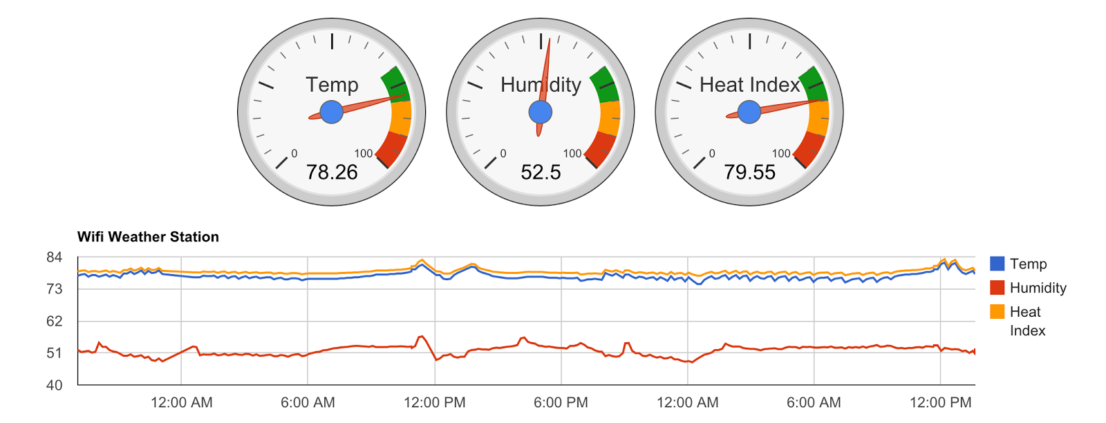
For web interface, Google Chart is used to draw gauge and graph to show historical change of temperature, humidity, and heat index.

Instructions


Setup hardware

For uploading


Here is a wiring information to upload sketch to ESP8266 using USB to TTL converter. Since my converter is 5v version, I used another power supply to provide 3.3v to ESP8266. GPIO 0 should be pulled down to the ground for uploading.

BE CAREFUL! ESP8266 works with only 3.3v, not 5v!


For running


Connect ESP8266 to DHT22 temperature sensor. GPIO 2 pin of ESP8266 is used to read measured data of DHT22.


Step 1. Create 'free data stream' at data.sparkfun.com


Visit https://data.sparkfun.com/ and click 'CREATE' menu to create a 'free data stream'. It's like an identifier for your data to read and write. One interesting feature of data.sparkfun.com is that it doesn't require you to create or activate any account. Just create 'free data stream'. Just remember that no more than 100 requests within 15 minutes window are allowed. On average, one request is allowed every 9 seconds. Check here for detail.


Among several fields in the creation form, 'Fields' and 'Stream Alias' are important. Fields are actual variable name for data when you send it with HTTP GET request. 'Stream Alias' is a name which can be used in URL to retrieve data from cloud.


Once you finish creating 'stream', it provides several information such as private key, public key and simple instructions on how to send and retrieve data. Don't loose them, you need them to proceed to the next step.

Step 2. Upload Sketch


For this step, you need those information at hand,

-SSID & Password of you Access Point
-List of field names you typed in 'Fields' in the creation form in Step 1
-Public Key from Step 1
-Private Key from Step 1

In this example, we used 3 fields to send data to cloud,

-temp: for temperature value measured in DHT22
-hum: for humidity value measured in DHT22
-hidx: for heat index calculated in the sketch

HTTP GET request for sending data looks like this,

data.sparkfun.com/input/YOUR_PUBLIC_KEY?private_key=YOUR_PRIVATE_KEY&temp=82.04&hum=53.10&hidx=83.29

Modify those values in the sketch according to your configuration. Then, compile and upload to ESP8266 using USB to TTL converter. If you face errors on Mac machine, refer to http://hpclab.blogspot.com/2015/06/esp8266-arduino-ide-on-mac-os-x.html for solution.

Once finish uploading, open 'Serial Monitor' in Arduino IDE, then you will see something like this,


To verify whether the data has been transmitted and stored in cloud without error, type this URL in web browser.

https://data.sparkfun.com/streams/YOUR_PUBLIC_KEY

You will see this kind of output if everything has gone well.


Step 3. Create HTML file


For this step, you need this information at hand,

-Public key from Step 1

Modify the value of public_key to your own key in example HTML file for web interface. Basically, it retrieves data in JSON format from cloud, then pass it to Google Chart API for drawing chart. In this example, gauge chart and line chart are used for demonstration.


Results


Open HTML file with web browser, then you will see this chart right away. If you would like to access web interface from anywhere in the world, then, just upload this HTML file to your web site. It does not require any additional files or libraries or anything, just one single HTML file.  That's it!


References

Tuesday, June 9, 2015

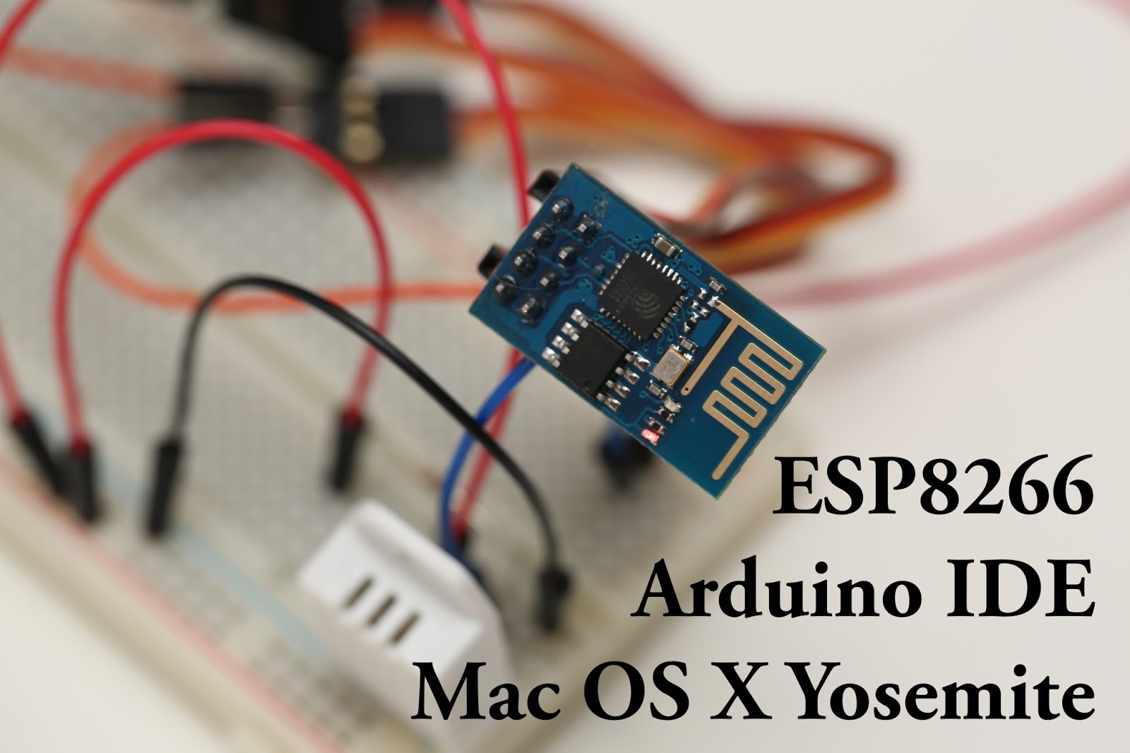
ESP8266 Arduino IDE on Mac OS X Yosemite 10.10.3


Introduction


How to program ESP8266 with Arduino IDE on Mac OS X Yosemite 10.10.3


Purpose


This article provides a walkaround for using Arduino IDE to program ESP8266 on Mac OS X Yosemite 10.10.3.


Environment

To be able to follow this article, make sure your environment is same as below.

1. OS X Yosemite 10.10.3
2. Arduino IDE 1.6.4
3. ESP8266 Package for Arduino IDE 1.6.4-673-g8cd3697 
    *Refer to https://github.com/esp8266/Arduino for more information about this package 

FYI, I used USB to TTL Serial Cable Adapter Chipset PL2303HX' from ebay. Different chipset may produce different output.

What is problem?


If you click 'upload' on Arduino IDE, then you most likely end up with these errors and your ESP8266 won't be programmed properly.

Sketch uses 240,292 bytes (45%) of program storage space. Maximum is 524,288 bytes.
Uploading 33216 bytes from /var/folders/94/rt16wrlj14ng3z47m6q85qgr0000gn/T/build5456473246941663239.tmp/wifi-weather-sensor.cpp_00000.bin to flash at 0x00000000
error: failed reading byte
warning: espcomm_send_command: cant receive slip payload data
warning: espcomm_send_command(FLASH_DOWNLOAD_BEGIN) failed

It means that compilation has been completed successfully, but, there is an error while it is uploading compiled binaries to ESP8266. To fix the problem, we need to identify who is taking care of the 'uploading'? It's a little program, called 'esptool' and full path to it is

/Users/$USER/Library/Arduino15/packages/esp8266/tools/esptool/0.4.4/esptool

Solution

Since 'esptool' does not work correctly, we need to use alternative tool to upload binaries to ESP8266. One of the solution is 'esptool.py', which is a little python program for uploading and it works fine on Mac.

Follow these steps to install 'esptool.py', then, inform Arduino IDE to use 'esptool.py' instead of 'esptool' to upload binary to EPS8266.


Step 1: Close Arduino IDE completely


Step 2: Install esptool.py

Follow installation instruction at https://github.com/themadinventor/esptool

In my case, I just downloaded a single python file 'esptool.py', then, installed pySerial, which esptool.py requires to run. Make a note where you installed esptool.py. We need full path to it in Step 3.

All installation is done. Now, we just need to ask Arduino IDE to use 'esptool.py' we've just installed instead of 'esptool'

Step 3: Modify platform.txt file

By modifying 'platform.txt' file, we can specify 'esptool.py' as an uploading tool. 

In my case, I installed 'esptool.py' at /Users/$USER/tmp/esp8266/esptool/esptool.py"

Just open platform.txt located at 

/Users/$USER/Library/Arduino15/packages/esp8266/hardware/esp8266/1.6.4-673-g8cd3697/platform.txt

and move to the end of file. Then you will se this line.

tools.esptool.upload.pattern="{path}/{cmd}" {upload.verbose} -cd {upload.resetmethod} -cb {upload.speed} -cp "{serial.port}" -ca 0x00000 -cf "{build.path}/{build.project_name}_00000.bin" -ca 0x10000 -cf "{build.path}/{build.project_name}_10000.bin"

Change it like this way


#tools.esptool.upload.pattern="{path}/{cmd}" {upload.verbose} -cd {upload.resetmethod} -cb {upload.speed} -cp "{serial.port}" -ca 0x00000 -cf "{build.path}/{build.project_name}_00000.bin" -ca 0x10000 -cf "{build.path}/{build.project_name}_10000.bin"
tools.esptool.upload.pattern="/Users/$USER/tmp/esp8266/esptool/esptool.py" --port "{serial.port}" write_flash 0x00000 "{build.path}/{build.project_name}_00000.bin"  0x10000  "{build.path}/{build.project_name}_10000.bin"

You can change the full path to esptool.py to wherever you installed esptool.py on your system.

Step 4: Open Arduino IDE and Load esp8266 example sketch


Set 'Board' to 'Generic ESP8266' and 'Port' to wherever ESP8266 connected to currently. It is '/dev/cu.usbserial/' in my case.

Click 'upload' on Arduino IDE, then you will see following message if everything goes well.

Sketch uses 240,292 bytes (45%) of program storage space. Maximum is 524,288 bytes.
/Users/$USER/tmp/esp8266/esptool/esptool.py --port /dev/cu.usbserial write_flash 0x00000 /var/folders/94/rt16wrlj14ng3z47m6q85qgr0000gn/T/build8386918307655313675.tmp/wifi-weather-sensor.cpp_00000.bin 0x10000 /var/folders/94/rt16wrlj14ng3z47m6q85qgr0000gn/T/build8386918307655313675.tmp/wifi-weather-sensor.cpp_10000.bin 
Connecting...
Erasing flash...

Writing at 0x00000000... (3 %) 
Writing at 0x00000400... (6 %) 
Writing at 0x00000800... (9 %) 
.
.
.
Writing at 0x00007400... (90 %) 
Writing at 0x00007800... (93 %) 
Writing at 0x00007c00... (96 %) 
Writing at 0x00008000... (100 %)
Erasing flash...

Writing at 0x00010000... (0 %) 
Writing at 0x00010400... (0 %) 
Writing at 0x00010800... (1 %) 
.
.
.
Writing at 0x00041c00... (98 %) 
Writing at 0x00042000... (99 %) 
Writing at 0x00042400... (99 %) 
Writing at 0x00042800... (100 %)

Leaving...

Now, ESP8266 starts to run with newly installed sketch.

In the following post, I will describe how I made a wifi weather monitoring system using ESP8266, DHT22 sensor, data.sparktfun.com, and Google Chart APIs.

Thanks

References


Monday, June 1, 2015

Arduino implementation of La Crosse TX6U

Introduction

Arduino implementation of La Crosse TX6U Remote Temperature Sensor with Arduino Uno, DHT22 temperature humidity sensor, 433Mhz Transmitter.


Purpose

Low cost remote temperature sensor comaptible with La Crosse Weather Station
Source at github

La Crosse Weather Station WS-9016U

WS-9016U consists of Indoor Weather Station(WS-9016U) and Remote Temperature Sensor(TX6U)
Acording to WS-9016U & TX6U manual,
  • Power up remote sensor first, then, power up base station
  • Range of 80 feet

WS-9016U Indoor Weather Station,

  • can have up to 3 remote sensors

TX6U Remote Temperature Sensor,

  • transmits temperature every 1 minute

Parts

Hardware

  • Arduino Uno
  • DHT22 Temperature Humidity Sensor
  • 433Mhz Transmitter
  • 10k resistor(pull up)
  • Breadboard

Software

Wiring

Testing

License and Credits

tx6u-arduino is based on Adafruit's DHT library and jremington's TX6U_send.ino source code.
tx6u-arduino is distributed under GPL License.

Reference

Source at github

Friday, July 20, 2012

Is GPU good for large vector addition?

Introduction

With more than one GPU programming interfaces available, there is a great interest in converting regular program to GPU program with two frequently asked questions.

  1. How much performance improvement can we expect from it?
  2. Which programming interface is better than others?

In this post, the performance of CPU and GPU are compared for vector addition and matrix multiplication, which are widely used building blocks for scientific application.

Additionally, the performance of OpenCL, CUDA, and PGI Accelerator on NVIDIA's M2050GPU are analyzed to compare different GPU programming interfaces.

1. Is GPU faster than CPU?

No - for vector addition

Yes - for matrix multiplication

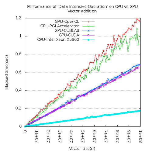
Figure 1 shows 'elapsed time' for vector addition on CPU and GPU. CPU is about 4 times faster than GPU in this experiment.


Figure 1. CPU is faster than GPU for vector addition

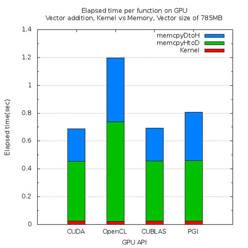
Figure 2. Elapsed time per function on GPU

Large vectors need to be copied from CPU memory to GPU memory through relatively slow PCIe bus and it overshadows the higher computational capability of GPU. Figure 2 tells us that most of time on GPU are used to copy data.

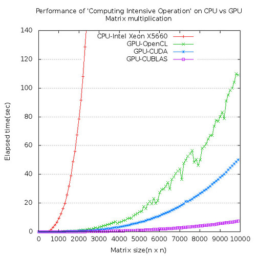
However, for matrix multiplication, GPU is 200 times or more faster than CPU. Computing intensive calculation such as matrix multiplication is best candidate for GPU.

Figure 3. GPU is extremely faster than CPU for matrix multiplication

Most of times are consumed for computations and data transfer time is almost negligible for matrix multiplication on GPU.

Figure 4. Elapsed time per function on GPU

2. Is OpenCL better than CUDA?

Yes for compatibility

??? for performance

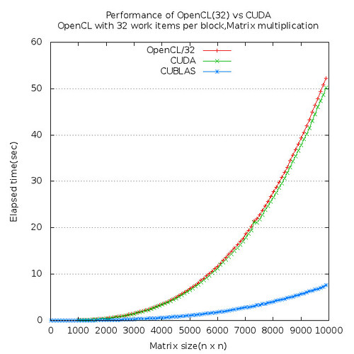
CUDA is about 5% faster than OpenCL for matrix multiplication in this experiment on NVIDIA M2050 platform.

Conclusion

To be able to get maximum performance out of NVIDIA GPU, try to take advantage of CUBLAS as much as possible. If there is any chance that your program need to be running on different GPU platform such as AMD or INTEL, etc, then use OpenCL for compatibility.

If you are interested in full article about this experiment, check here.