Introduction
Voice control ESP8266 with Google Assistant


Purpose
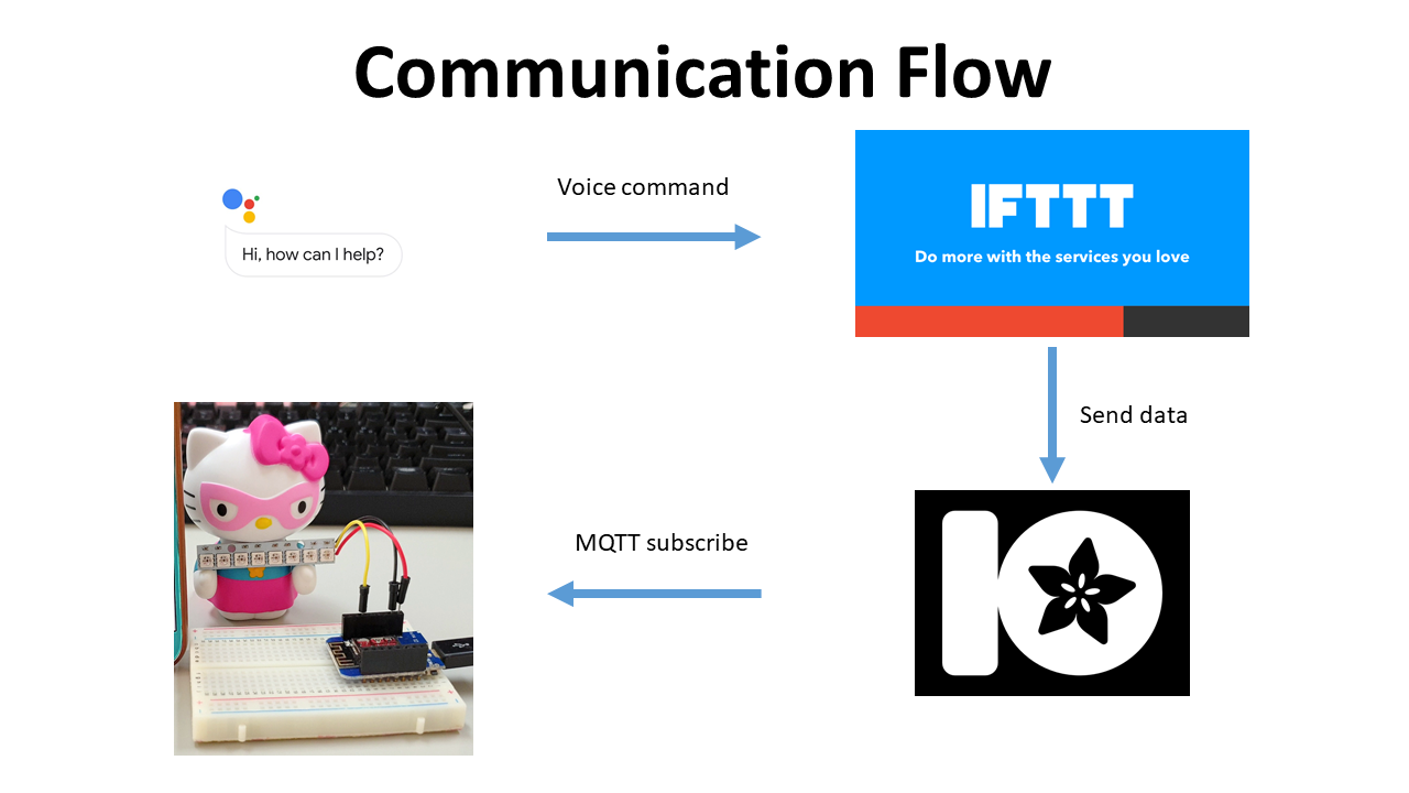
The aim of this project is to voice control ESP8266 with Google Assistant. We talk to Google Assistant app. Once Google Assistant hear our voice command, it will communicate with IFTTT. Then, IFTTT forwards command to Adafruit MQTT broker. Finally, ESP8266 receives the command through MQTT subscribe function and executes it.
This project requires multiple services to complete the mission. First, it requires Google Assistant app on your phone. Then, we need to create IFTTT account and Adafruit MQTT broker account. In IFTTT, create an applet to link Google Assistant and MQTT broker, so, IFTTT can forward our command from Google Assistant to MQTT broker. Wemos receives a messge from MQTT broker using subscribe function. The whole communication flow looks like this,
Features
This project requires multiple services to complete the mission. First, it requires Google Assistant app on your phone. Then, we need to create IFTTT account and Adafruit MQTT broker account. In IFTTT, create an applet to link Google Assistant and MQTT broker, so, IFTTT can forward our command from Google Assistant to MQTT broker. Wemos receives a messge from MQTT broker using subscribe function. The whole communication flow looks like this,
Prerequisites
- ESP8266 package for Arduino IDE
- EPS8266 Sketch Data Upload
- IFTTT
- Adafruit MQTT broker
- Adafruit_NeoPixel Library for controlling single-wire LED pixels (NeoPixel, WS2812, etc.)
Hardware
- Wemos D1 mini : US$1.77 on Aliexpress
- NeoPixel compatible LED stick: https://www.adafruit.com/product/1426
Step 1. Setup hardware
Normally, LED stick has VCC, GND, DATA pin. Wiring is very simple, just connect DATA of LED stick to D1 of Wemos.

Step 2. Create IFTTT account and Adafruit MQTT account
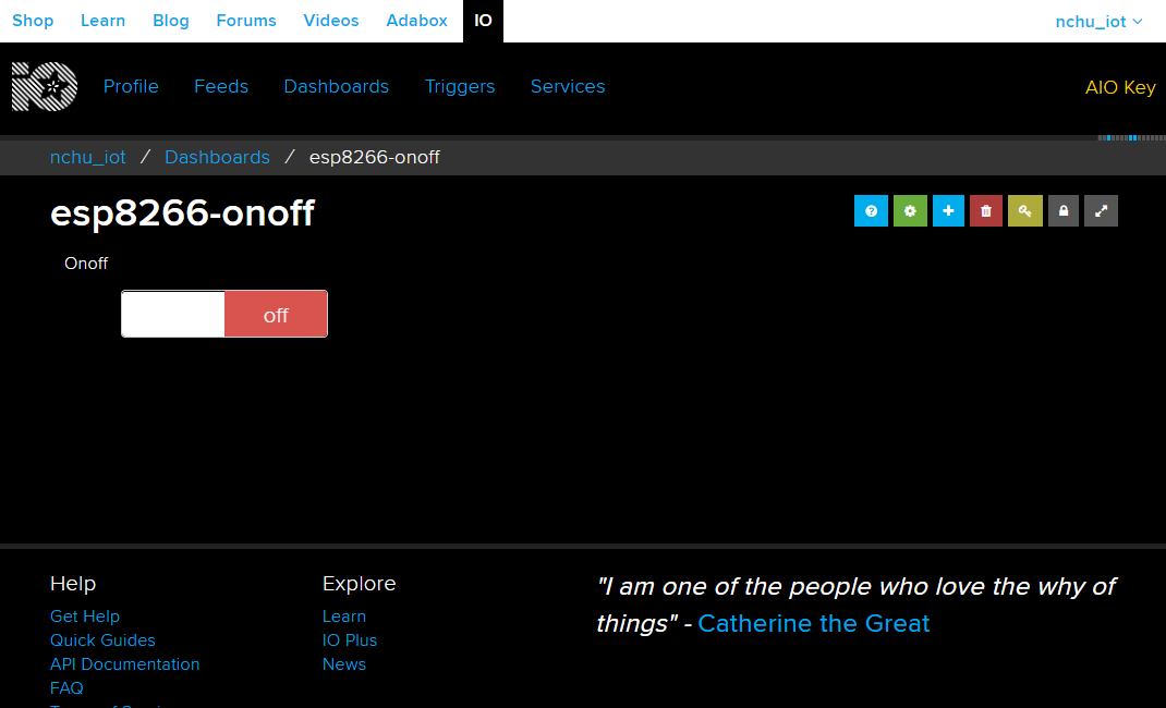
After creating Adafruit MQTT account, create a "feed" and dashboard for it just like this. We are going to use this dashboard to test communication between Wemos and MQTT broker later.
Useful tutorial about how to create a "feed" on MQTT broker is available here https://learn.adafruit.com/adafruit-io-basics-digital-output?view=all
Then, create two applets on IFTTT, one is for "turning off the light" and the other is for "turning on the light". Useful tutorial is here https://www.electronicwings.com/nodemcu/control-home-appliances-using-google-assistant
Step 3. Upload sketch to Wemos D1 mini
This step is to upload sketch to Wemos as usual. In the following sketch, following values need to be modified with your own.
- WIFI_SSID : Name of WiFi router
- WIFI_PASS : Password of WiFi router
- AIO_USERNAME : Value of 'IO_USERNAME' of MQTT broker
- AIO_KEY : Value of 'IO_KEY' of the MQTT broker
After uploading firmware, Wemos restarts itself automatically. Once Wemos D1 has restarted, serial monitor shows a welcome message and IP address of Wemos. It displays detail about the command whenever it receives new one. In this example, there are two different commands; on and off.
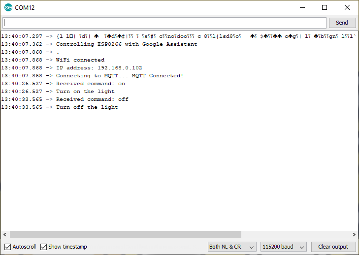
Right after upload sketch, it is recommended to test whether Wemos is working with MQTT broker without problem by clicking onoff switch on MQTT broker dashboard. It would be good news if console message shows the correct command whenever you click the switch on dashboard.

After confirming above step, now it is time to test the system altogether.

- EPS8266 Sketch Data Upload
- IFTTT
- Adafruit MQTT broker
- Adafruit_NeoPixel Library for controlling single-wire LED pixels (NeoPixel, WS2812, etc.)
Requirements
- Wemos D1 mini : US$1.77 on Aliexpress
- NeoPixel compatible LED stick: https://www.adafruit.com/product/1426
Instructions
Normally, LED stick has VCC, GND, DATA pin. Wiring is very simple, just connect DATA of LED stick to D1 of Wemos.
Step 2. Create IFTTT account and Adafruit MQTT account
After creating Adafruit MQTT account, create a "feed" and dashboard for it just like this. We are going to use this dashboard to test communication between Wemos and MQTT broker later.
Useful tutorial about how to create a "feed" on MQTT broker is available here https://learn.adafruit.com/adafruit-io-basics-digital-output?view=all
Then, create two applets on IFTTT, one is for "turning off the light" and the other is for "turning on the light". Useful tutorial is here https://www.electronicwings.com/nodemcu/control-home-appliances-using-google-assistant
Step 3. Upload sketch to Wemos D1 mini
This step is to upload sketch to Wemos as usual. In the following sketch, following values need to be modified with your own.
- WIFI_SSID : Name of WiFi router
- WIFI_PASS : Password of WiFi router
- AIO_USERNAME : Value of 'IO_USERNAME' of MQTT broker
- AIO_KEY : Value of 'IO_KEY' of the MQTT broker
Results
Right after upload sketch, it is recommended to test whether Wemos is working with MQTT broker without problem by clicking onoff switch on MQTT broker dashboard. It would be good news if console message shows the correct command whenever you click the switch on dashboard.
After confirming above step, now it is time to test the system altogether.
References
- IFTTT
- Adafruit MQTT broker
- Adafruit_NeoPixel Library for controlling single-wire LED pixels (NeoPixel, WS2812, etc.)
- IoT Laboratory: ESP8266-based WiFi MQTT air quality monitoring system using PMS7003 sensor
- IoT Laboratory: ESP8266-based WiFi air quality monitoring system using PMS7003 sensor
Source codes at github- Adafruit MQTT broker
- Adafruit_NeoPixel Library for controlling single-wire LED pixels (NeoPixel, WS2812, etc.)
- IoT Laboratory: ESP8266-based WiFi MQTT air quality monitoring system using PMS7003 sensor
- IoT Laboratory: ESP8266-based WiFi air quality monitoring system using PMS7003 sensor
No comments:
Post a Comment